_edited_edit.png)
In the era of digital electronics, shift registers and ring counters are crucial components that serve various roles in data handling, storage, and sequencing operations. Both of these devices are integral to the design and functionality of numerous digital systems. This blog will delve into the principles, types, and applications of shift registers and ring counters, shedding light on their importance in digital electronics.
1. Shift Register Counter:

A shift register counter is a basic counter where the data is shifted from one flip-flop to the next on each clock pulse.
The output is typically taken from the last flip-flop (Q output).
It can be used for simple counting or for generating specific sequences depending on the initial state and how the data is shifted.
Example:
Consider a 3-bit shift register counter with a serial input (Din) and a clock (CLK) signal. Here's how it operates:
On each clock pulse, the data at Din is loaded into the first flip-flop (Q0).
Simultaneously, the existing data in each flip-flop is shifted one position to the right. So, Q0's value moves to Q1, Q1's value moves to Q2, and the previous value in Q2 is lost (unless it's fed back to Din for a specific sequence).
Truth Table:
(Assuming Din is always 0 for illustration)
CLK | Din | Q2 | Q1 | Q0 | Count (Decimal) |
0 | 0 | X | X | X | - |
1 | 0 | 0 | X | X | 0 |
2 | 0 | 0 | 0 | X | 0 |
3 | 0 | 0 | 0 | 0 | 0 |
2. Ring Counter:

A ring counter is a type of shift register counter where the output of the last flip-flop (Qn) is fed back to the input of the first flip-flop (D0) instead of being lost.
This creates a "ring" of data circulation.
As the clock pulses, the data pattern circulates within the ring, resulting in a sequence of binary values at the output.
The number of distinct states in the sequence (modulus) is equal to the number of flip-flops (n).
Example:
Consider a 3-bit ring counter:
Initially, all flip-flops can be reset (000).
On each clock pulse, the data in the ring shifts one position, eventually completing a full cycle and returning to the initial state after n clock pulses (3 in this case).
Truth Table:
CLK | Q2 | Q1 | Q0 | Count (Binary) |
0 | 0 | 0 | 0 | 000 |
1 | 0 | 0 | 1 | 001 |
2 | 0 | 1 | 0 | 010 |
3 | 1 | 0 | 0 | 100 |
3. Twisted Ring Counter (Johnson Counter):
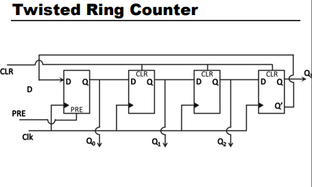
A twisted ring counter (also known as a Johnson counter) is similar to a ring counter, but the output of the last flip-flop (Qn) is inverted before being fed back to the input of the first flip-flop (D0).
This creates a sequence with twice the number of distinct states as a regular ring counter (2^n).
After a full cycle, the twisted ring counter doesn't return to the initial state but reaches a complementary state.
Example:
Consider a 3-bit twisted ring counter:
Initially, all flip-flops can be reset (000).
On each clock pulse, the inverted output of the last flip-flop is shifted into the first position.
This results in a sequence with six distinct states before returning to a complementary state of the initial state (111).
Truth Table:
S.no. | Q2 | Q1 | Q0 | Count (Binary) |
0 | 0 | 0 | 0 | 000 |
1 | 0 | 0 | 1 | 001 |
2 | 0 | 1 | 0 | 010 |
Comments